
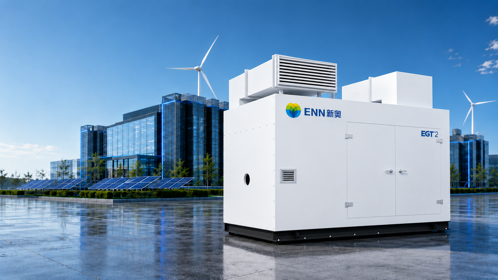
| Parameters | Simple Cycle | Regenerative Cycle | |
|---|---|---|---|
| Electrical performance[1] | Rated power output kW | 128 | 110 |
| Rate power generation efficiency % | 13.9 | 22.1 | |
| Fuel requirements | Fuel type | Natural gas | Natural gas |
| Fuel calorific value range MJ/Nm3 | 30~37 | 30~37 | |
| Fuel supply pressure bar(g) [9] | 6~8 | 6~8 | |
| Fuel flow rate at rated condition Nm3/h [2] | 98 | 53 | |
| Heat rate kJ/kWh | 25899 | 16290 | |
| Tail gas | NOx emission ppmv | =<25 (@15% oxygen content) | =<25 (@15% oxygen content) |
| Flue gas flow rate kg/s | 1.17 | 1.14 | |
| Flue gas flow rate m3/h (operating condition) | 10981 | 6749 | |
| Flue gas flow rate Nm3/h (standard condition) [10] | 3338 | 3238 | |
| Flue gas temperature °C | 604 | 308 | |
| Dimensions & weight | L x W x H mm | 3200 x 2202 x 3460 | 5536 x 2202 x 3460 |
| Weight t | 7.4 | 8.1 | |
| Environmental performance | Noise (at lm distance) dB(A) | =< 85 | =< 85 |
| CHP | Steam output t/h [3] | 0.8 | – |
| Drying heat kW [4] | 624 | 225 | |
| Hot water output t/h [5] | 12.5 | 5.1 | |
| CCHP | Cooling capacity: kW [6] | 863 | 178 |
| Cooling capacity: 10,000 kcal/h [6] | 74 | 15 | |
| Heating capacity: kW [7] | 552 | 182 | |
| Heating capacity: 10,000 kcal/h [7] | 48 | 16 | |
| Energy supply area: m2 [8] | 9600~21600 | 2000~4400 | |
Notes:
[1] Rated operating performance under standard conditions (15°C, 101.325 kPa, 60% relative humidity).
[2] Derived based on the lower heating value of natural gas at 34 MJ/Nm3 (where the standard conditions for Nm3 are 0°C and 325 kPa).
[3] Steam output is based on a steam pressure of 0.8 MPa(g) and a steam temperature of 175°C.
[4] Drying heat is based on flue gas heat at temperatures above 120°C.
[5] Hot water output is derived under the conditions of an inlet water temperature of 15°C, an outlet water temperature of 60°C, and a flue gas outlet temperature of 75°C.
[6] Cooling capacity is obtained based on an absorption chiller exhaust gas temperature of 160°C, with a simple cycle COP of LS and a heat recovery cycle COP of 1.0.
[7] Heating capacity is derived based on an absorption chiller exhaust gas temperature of 145°C and a COP of 0.93.
[8] Energy supply area is calculated based on a cooling load of 40~90 W/m2, which is for reference only. Due to variations in the load of different buildings, the actual energy supply area shall be determined according to the specific conditions of the building.
[9] The fuel supply pressure here refers to the pressure required for gas to be supplied directly to the gas turbine
(without a compressor) or supplied to the gas turbine after being compressed by a compressor.
[10] This refers to the flue gas volume flow rate under standard conditions (0°C, 101.325 kPa).