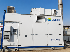
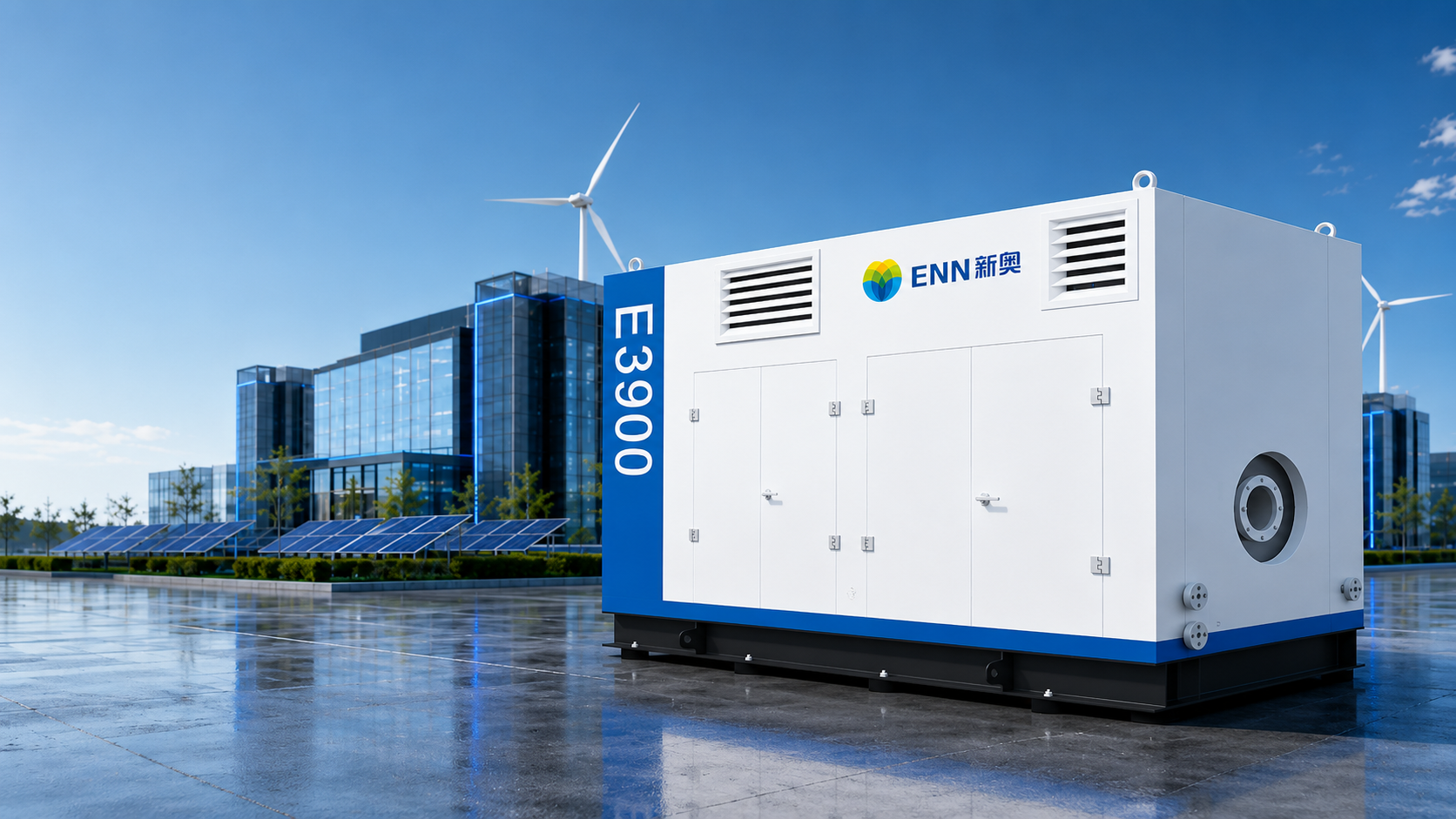
| Parameters | Simple Cycle | Regenerative Cycle | |
|---|---|---|---|
| Electrical performance[1] | Rated power output kW | 396 | 3446 |
| Rate power generation efficiency % | 17.1 | 26.5 | |
| Fuel requirements | Fuel type | Natural gas | Natural gas |
| Fuel calorific value range MJ/Nm3 | 30~37 | 30~37 | |
| Fuel supply pressure bar(g) [9] | 6~8 | 6~8 | |
| Fuel flow rate at rated condition Nm3/h [2] | 245 | 138 | |
| Heat rate kJ/kWh | 21053 | 13585 | |
| Tail gas | NOx emission ppmv | =<25 (@15% oxygen content) | =<25 (@15% oxygen content) |
| Flue gas flow rate kg/s | 2.9 | 2.85 | |
| Flue gas flow rate m3/h (operating condition) | 25891 | 17040 | |
| Flue gas flow rate Nm3/h (standard condition) [10] | 8174 | 8003 | |
| Flue gas temperature °C | 592 | 308 | |
| Dimensions & weight | L x W x H mm | 5200 x 2500 x 4709 | 8189 x 2500 x 4709 |
| Weight t | 16 | 17.5 | |
| Environmental performance | Noise (at lm distance) dB(A) | =< 35 | =< 35 |
| CHP | Steam output t/h [3] | 1.9 | 0.6 |
| Drying heat kW [4] | 1514 | 566 | |
| Hot water output t/h [5] | 30.3 | 12.8 | |
| CCHP | Cooling capacity: kW [6] | 2089 | 448 |
| Cooling capacity: 10,000 kcal/h [6] | 180 | 38 | |
| Heating capacity: kW [7] | 1338 | 458 | |
| Heating capacity: 10,000 kcal/h [7] | 115 | 39 | |
| Energy supply area: m2 [8] | 23200~52200 | 5000~11200 | |
Notes:
[1] Rated operating performance under standard conditions (15°C, 101.325 kPa, 60% relative humidity).
[2] Derived based on the lower heating value of natural gas at 34 MJ/Nm3 (where the standard conditions for Nm3 are 0°C and 101.325 kPa).
[3] Steam output is based on a steam pressure of 0.8 MPa(g) and a steam temperature of 175°C.
[4] Drying heat is based on flue gas heat at temperatures above 120°C.
[5] Hot water output is derived under the conditions of an inlet water temperature of 15°C, an outlet water temperature of 60°C, and a flue gas outlet temperature of 75°C.
[6] Cooling capacity is obtained based on an absorption chiller exhaust gas temperature of 160°C, with a simple cycle COP of LS and a heat recovery cycle COP of 1.0.
[7] Heating capacity is derived based on an absorption chiller exhaust gas temperature of 145°C and a COP of 0.93.
[8] Energy supply area is calculated based on a cooling load of 40~90 W/m2, which is for reference only. Due to variations in the load of different buildings, the actual energy supply area shall be determined according to the specific conditions of the building.
[9] The fuel supply pressure here refers to the pressure required for gas to be supplied directly to the gas turbine (without a compressor) or supplied to the gas turbine after being compressed by a compressor.
[10] This refers to the flue gas volume flow rate under standard conditions (0°C, 101.325 kPa).
| Fuel type | Energy Solution | Delivery time |
|---|---|---|
| Low-calorific-value vent gas | One E390 gas turbine+ One 500 Nm3/h compressor+ One 1500 kW flue gas heat exchanger | November 2023 |
It uses low-calorific-value vent gas generated from oilfield gas flooding recovery to generate electricity, avoiding environmental pollution and resource waste caused by direct flaring. The waste heat from the gas turbine is used to produce hot water for crude oil heating, replacing the original electric boiler and reducing energy consumption costs.
Customer Value: